|
 
- UID
- 1023166
- 性别
- 男
- 来自
- 燕山大学
|

ST STM320518-EVAL ARM Cortex-M0 MCU开发方案
关键词: arm , Cortex-M0 , MCU , ST , STM320518-EVAL
ST公司的STM32F051xx系列采用高性能ARM Cortex-M0 32位RISC内核,工作频率48MHz,具有高速嵌入存储器(多达64KB闪存和多达8KB SRAM)以及扩展外设和I/O口.所有器件具有标准通信接口(多达两个I2C,两个SPI,一个I2S,一个HDMI CEC和多达两个USART),一个12位ADC,一个12位DAC,多达5个通用16位计时器,一个32位计时器和PWM计时器.主哟用在应用控制和用户接口,手持设备,A/V接收器和DTV,PC外设,游戏和GPS平台,PLC,逆变器,打印机,扫描仪,告警系统,视频互连和HVAC等.本文介绍了STM32F051xx主要特性,方框图和时钟子系统方框图,以及STM320518-EVAL评估板主要特性,方框图,电路图和PCB布局图.
The STM32F051xx family incorporates the high-performance ARM Cortex-M0 32-bit RISC core operating at a 48 MHz frequency, high-speed embedded memories (Flash memory up to 64 Kbytes and SRAM up to 8 Kbytes), and an extensive range of enhanced peripherals and I/Os. All devices offer standard communication interfaces (up to two I2Cs, two SPIs, one I2S, one HDMI CEC, and up to two USARTs), one 12-bit ADC, one 12-bit DAC, up to five general-purpose 16-bit timers, a 32-bit timer and an advanced-control PWM timer.
The STM32F051xx family operates in the -40 to +85 C and -40 to +105 C temperature ranges, from a 2.0 to 3.6 V power supply. A comprehensive set of power-saving modes allows the design of low-power applications.
The STM32F051xx family includes devices in three different packages ranging from 32 pins to 64 pins. Depending on the device chosen, different sets of peripherals are included. The description below provides an overview of the complete range of peripherals proposed in this family. These features make the STM32F051xx microcontroller family suitable for a wide range of applications such as application control and user interfaces, handheld equipment, A/V receivers and digital TV, PC peripherals, gaming and GPS platforms, industrial applications, PLCs, inverters, printers, scanners, alarm systems, video intercoms, and HVACs
STM32F051xx主要特性:
Operating conditions:
Voltage range: 2.0 V to 3.6 V
ARM 32-bit Cortex-M0 CPU (48 MHz max)
Memories
16 to 64 Kbytes of Flash memory
8 Kbytes of SRAM with HW parity checking
CRC calculation unit
Clock management
4 to 32 MHz crystal oscillator
32 kHz oscillator for RTC with calibration
Internal 8 MHz RC with x6 PLL option
Internal 40 kHz RC oscillator
Calendar RTC with alarm and periodic wakeup from Stop/Standby
Reset and supply management
Power-on/Power down reset (POR/PDR)
Programmable voltage detector (PVD)
Low power Sleep, Stop, and Standby modes
VBAT supply for RTC and backup registers
5-channel DMA controller
1 x 12-bit, 1.0 us ADC (up to 16 channels)
Conversion range: 0 to 3.6V
Separate analog supply from 2.4 up to 3.6 V
Two fast low-power analog comparators with programmable input and output
One 12-bit D/A converter
Up to 55 fast I/Os
All mappable on external interrupt vectors
Up to 36 I/Os with 5 V tolerant capability
Up to 18 capacitive sensing channels supporting touchkey, linear and rotary touch sensors
96-bit unique ID
Serial wire debug (SWD)
Up to 11 timers
One 16-bit 7-channel advanced-control timer for 6 channels PWM output, with deadtime generation and emergency stop
One 32-bit and one 16-bit timer, with up to 4 IC/OC, usable for IR control decoding
One 16-bit timer, with 2 IC/OC, 1 OCN, deadtime generation and emergency stop
Two 16-bit timers, each with IC/OC and OCN, deadtime generation, emergency stop and modulator gate for IR control
One 16-bit timer with 1 IC/OC
Independent and system watchdog timers
SysTick timer: 24-bit downcounter
One 16-bit basic timer to drive the DAC
Communication interfaces
Up to two I2C interfaces; one supporting Fast Mode Plus (1 Mbit/s) with 20 mA current sink,SMBus/PMBus, and wakeup from STOP
Up to two USARTs supporting master synchronous SPI and modem control; one with ISO7816 interface, LIN, IrDA capability auto baud rate detection and wakeup feature
Up to two SPIs (18 Mbit/s) with 4 to 16 programmable bit frame, 1 with I2S interface multiplexed
HDMI CEC interface, wakeup on header reception
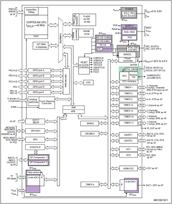
图1.STM32F051xx方框图
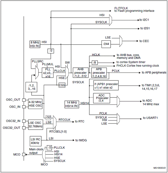
图2.STM32F051xx时钟子系统方框图
STM320518-EVAL评估板
The STM320518-EVAL evaluation board is designed as a complete demonstration and development platform for STMicroelectronic’s ARM cortex-M0 core-based
STM32F051R8T6 microcontroller. It features two I2Cs, two SPIs, two USARTs, a 12-bit ADC, a 12-bit DAC, two GP comparators, internal 8 KB SRAM and 64 KB Flash, touch sensing, CEC and SWD debugging support.
The full range of hardware features on the board is able to help you evaluate all peripherals (motor control connector, RS-232, RS-485, audio DAC, linear sensor, microphone ADC, TFT LCD, IrDA, IR LED, IR receiver, LDR, MicroSD card, CEC on two HDMI connectors, RF E2PROM, temperature sensor and so on) and develop your own applications. Extension headers make it possible to easily connect a daughterboard or wrapping board for your specific application.
An ST-LINK/V2 is integrated on the board as an embedded in-circuit debugger and programmer for the STM32 MCU.
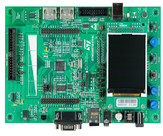
图3.STM320518-EVAL评估板外形图
STM320518-EVAL评估板主要特性:
● Three 5 V power supply options: power jack, ST-LINK/V2 USB connector or daughterboard
● Audio speaker and microphone connected to DAC and ADC of STM32F051R8T6
● 2 Gbyte or more SPI interface MicroSD card
● I2C compatible serial interface temperature sensor
● RF E2PROM
● RS-232 and RS-485 communication
● IrDA transceiver
● IR LED and IR receiver
● SWD debug support, ST-LINK/V2 embedded
● 240 x 320 TFT color LCD connected to SPI interface of STM32F051R8T6
● Joystick with 4-direction control and selector
● Reset, tamper and user buttons
● 4 color LEDs
● Extension connector for daughterboard or wrapping board
● MCU voltage choice fixed at 3.3 V or adjustable from 2 to 3.6 V
● Linear sensor
● Light dependent resistor (LDR)
● Potentiometer
● Two HDMI connectors with DDC and CEC
● Motor control connector
● Boards RoHS compliant
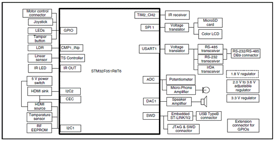
图4.STM320518-EVAL评估板硬件框图
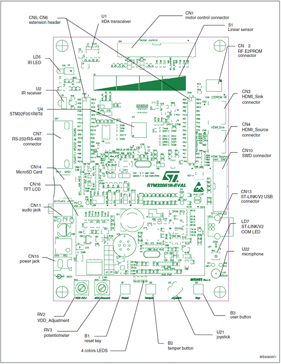
图5.STM320518-EVAL评估板布局图
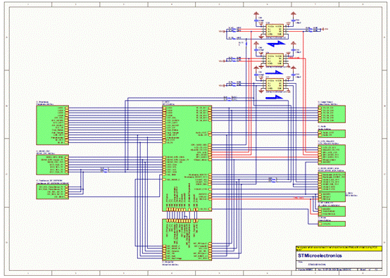
图6.STM320518-EVAL评估板电路图(1)
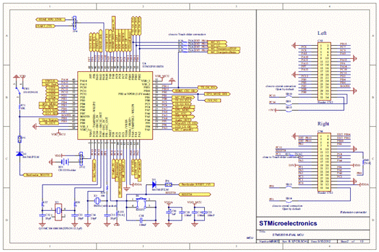
图7.STM320518-EVAL评估板电路图(2)
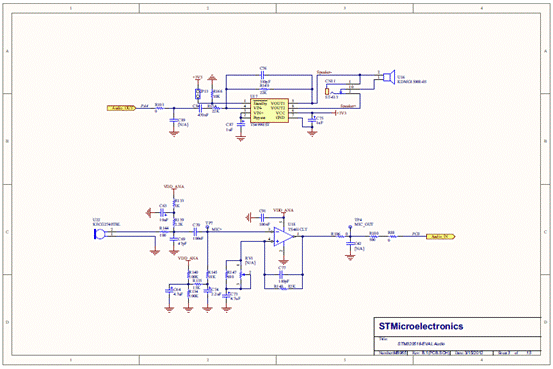
图8.STM320518-EVAL评估板电路图(3)

图9.STM320518-EVAL评估板电路图(4)
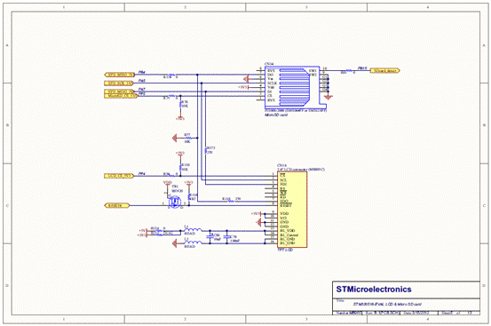
图10.STM320518-EVAL评估板电路图(5)
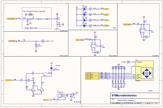
图11.STM320518-EVAL评估板电路图(6)
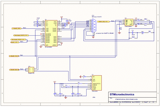
图12.STM320518-EVAL评估板电路图(7)
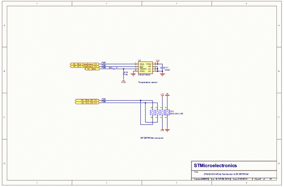
图13.STM320518-EVAL评估板电路图(8)
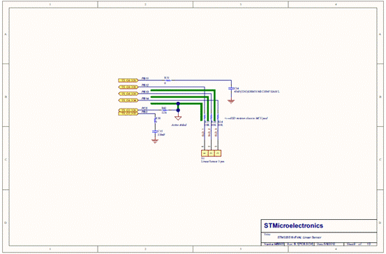
图14.STM320518-EVAL评估板电路图(9)
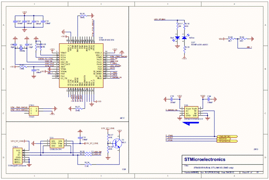
图15.STM320518-EVAL评估板电路图(10)
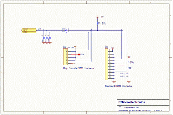
图16.STM320518-EVAL评估板电路图(11)
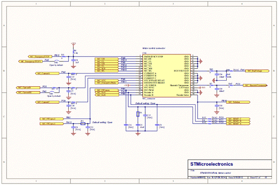
图17.STM320518-EVAL评估板电路图(12)
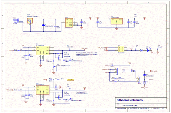
图18.STM320518-EVAL评估板电路图(13)
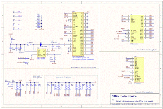
图19.STM320518-EVAL评估板电路图(14)
详情请见:
 DM00039193.pdf (1.07 MB, 下载次数: 19) 和 DM00039193.pdf (1.07 MB, 下载次数: 19) 和
 DM00052328.pdf (2.07 MB, 下载次数: 1) DM00052328.pdf (2.07 MB, 下载次数: 1) |
|
|

