Freescale TWR-56F8400 32位数字信号控制器开发方案
|
 
- UID
- 1023166
- 性别
- 男
- 来自
- 燕山大学
|

Freescale TWR-56F8400 32位数字信号控制器开发方案
关键词: Freescale , TWR-56F8400 , 数字信号控制器 , DSP
Freescale公司的MC56F84xx系列是基于32位DSP核的数字信号控制器(DSC),包括有高速度和高精度外设如312微微秒分辨率的PWM以及内置了PGA的双路高速12位ADC(取样频率高达3.3MSPS)和一个高精度16位ADC,具有极好的精度,检测和控制,适用于最大效率的数字电源转换和高端马达控制如太阳能逆变器,开关电源,智能传感器,无线充电和S-FSK动力线调制解调器等.本文介绍了MC56F84xx主要特性,系统方框图, TWR-56F8400 MCU模块主要特性,方框图,电路图和材料清单(BOM).
The MC56F84xx is based on our newly designed 32-bit DSP core. It is the market’s fastest digital signal-processing MCU offering exceptional precision, sensing and control for the most efficient digital power conversion and advanced motor control applications. The MC56F84xx includes advanced high-speed and high-accuracy peripherals such as high-resolution pulse width modulation (PWM) with 312 pico-second resolution and dual, high-speed 12-bit analog-to-digital converters (ADCs) with built-in PGA sampling up to 3.3 mega samples per second (Msps) and one high-precision 16-bit ADC. Faster application-specific control loops are driven via a high-speed 32-bit DSP core with single-cycle math computations, fractional arithmetic support and parallel moves.
MC56F84xx主要特性:
• This family of digital signal controllers (DSCs) is based on the 32-bit 56800EX core. Each device combines, on a single chip, the processing power of a DSP and the functionality of an MCU with a flexible set of peripherals to support many target applications:
Industrial control
– Home appliances
– Smart sensors
– Fire and security systems
– Switched-mode power supply and power management
– Uninterruptible Power Supply (UPS)
– Solar and wind power generator
– Power metering
– Motor control (ACIM, BLDC, PMSM, SR, stepper)
– Handheld power tools
– Circuit breaker
– Medical device/equipment
– Instrumentation
– Lighting
• DSC based on 32-bit 56800EX core
– Up to 60 MIPS at 60 MHz core frequency
– DSP and MCU functionality in a unified, C-efficient architecture
• On-chip memory
– Up to 160 KB (128 KB + 32 KB) flash memory, including up to 32 KB FlexNVM
– Up to 24 KB RAM
– Up to 2 KB FlexRAM with EEE capability
– 60 MHz program execution from both internal flash memory and RAM
– On-chip flash memory and RAM can be mapped into both program and data memory spaces
• Analog
– Two high-speed, 8-channel, 12-bit ADCs with dynamic x2, x4 programmable amplifier
– One 20-channel, 16-bit ADC
– Up to four analog comparators with integrated 6-bit
DAC references
– One 12-bit DAC
• PWMs and timers
– One eFlexPWM module with up to 24 PWM outputs
– Two 16-bit quad timer (2 x 4 16-bit timers)
– Two Periodic Interval Timers (PITs)
– One Quadrature Decoder
– Two Programmable Delay Blocks (PDBs)
• Communication interfaces
– Two high-speed queued SCI (QSCI) modules with
LIN slave functionality
– Two queued SPI (QSPI) modules
– Two SMBus-compatible I2C ports
– One flexible controller area network (FlexCAN) module
• Security and integrity
– Cyclic Redundancy Check (CRC) generator
– Computer operating properly (COP) watchdog
– External Watchdog Monitor (EWM)
• Clocks
– Two on-chip relaxation oscillators: 8 MHz (400 kHz at standby mode) and 32 kHz
– Crystal / resonator oscillator
• System
– DMA controller
– Integrated power-on reset (POR) and low-voltage interrupt (LVI) and brown-out reset module
– Inter-module crossbar connection
– JTAG/enhanced on-chip emulation (EOnCE) for unobtrusive, real-time debugging
• Operating characteristics
– Single supply: 3.0 V to 3.6 V
– 5 V–tolerant I/O
• LQFP packages:
– 48-pin
– 64-pin
MC56F84xx目标应用:
Connectivity
S-FSK Power Line Modem
Consumer
Wireless Charging
Industrial
Off-Grid Solar Power Inverters
Commercial Solar Power Inverters
Residential Solar Power Inverters
Fire and Security Systems
Switched Mode Power Supply
Smart Sensors
Arc Fault Detectors
Circuit Breakers
Power Quality Monitors
Motor Control
Brushed DC Motor
Brushless DC (BLDC) Motor
Permanent Magnet Synchronous Motor
3-Phase AC Induction Motor
1-Phase AC Induction Motor
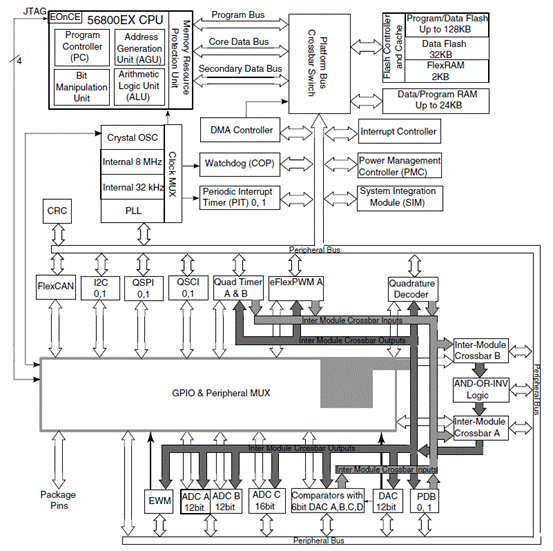
图1.MC56F84xx系统框图
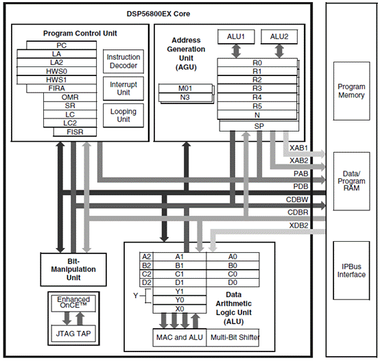
图2.56800EX 基本方框图
MC56F8400 Tower 32位MCU模块(TWR-56F8400)
The MC56F8400 Tower 32-bit MCU Module (TWR-56F8400) is an evaluation, demonstration and development board. The TWR-56F8400 can operate stand-alone or as the main control board in a Tower system with peripheral modules. It can also be used as the main control board with an APMOTOR56F8000E motor control board.
TWR-56F8400 MCU模块主要特性:
• 32 bit Digital Signal Controller module featuring MC56F84789
• Tower compatible
• Selectable Power sources: o USB on 56F8400 card
o Barrel connector on 56F8400 card
o Motor control board plug direct to 56F8400 card, no Tower connection, plug Motor control to nine volts
o Tower elevator board (USB or Barrel on Primary side)
• Filtered power for VDDA and VSSA on the 32-bit MC56F84789DSC
• MC56F84789 DSC (Digital Signal Controller) in an 100 LQFP package
• Optional 8 MHz crystal circuit for the MC56F84789 DSC
• 9 LEDs controlled by the MC56F84789 DSC
• Motor Control Board connector for the APMOTOR56F8000E motor control board
• Auxiliary Signal connector
• Four Thermistors for single ended or differential analog inputs to the MC56F84789 DSC
• CAN transceiver, header, and termination
• Two push buttons for user input or interrupts to the MC56F84789 DSC
• Reset push button for the MC56F84789 DSC
• JTAG header for the MC56F84789 DSC with header to disconnect from OSBDM/OSJTAG
• Headers to connect SCI signals to either USB bridge with CDC(one channel) or elevator board (two channels) or connect one to each
• Expansion via Primary Elevator connector
• MC9S08JM60 (‘JM60) MCU with a 4 MHz crystal provides: o Open Source Debug (OSBDM/OSJTAG) circuit
o USB to SCI bridge with CDC and other techniques supported by third parties
o Simultaneious OSBDM/OSJTAG and USB to SCI bridge functions with no header required to select
o Bootloader enable header allows easy upgrade to latest S08 firmware pushed down by CodeWarrior
o BDM header for the MC9S08JM60 MCU
o Status and Target Power indicator LEDs
o Control of semiconductor switch to enable power to board from USB
o Voltage translators between 5V MC9S08JM60 MCU chip and 3.3V MC56F84789 DSC chip
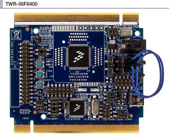
图3.TWR-56F8400 MCU模块外形图
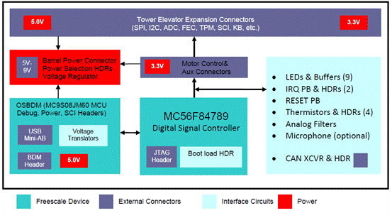
图4.TWR-56F8400 MCU模块方框图
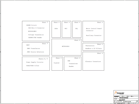
图5.TWR-56F8400框图
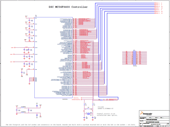
图6.TWR-56F8400电路图(1)
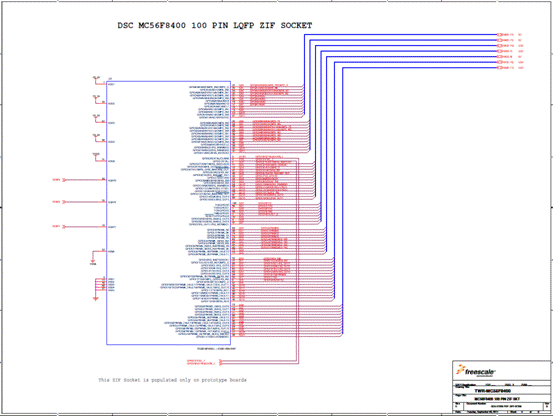
图7.TWR-56F8400电路图(2)
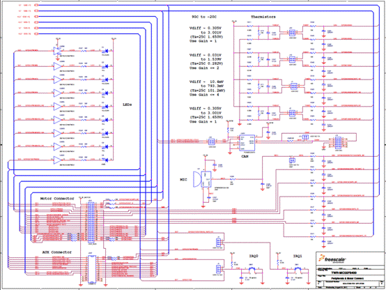
图8.TWR-56F8400电路图(3)
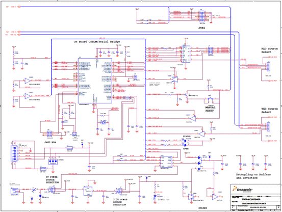
图9.TWR-56F8400电路图(4)
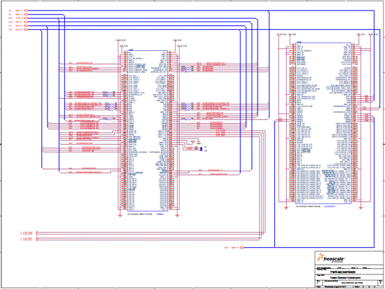
图10.TWR-56F8400电路图(5)
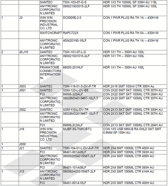
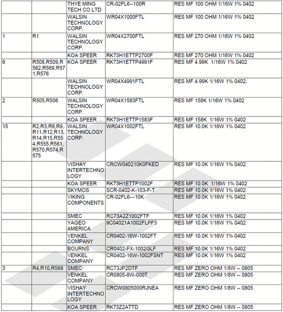
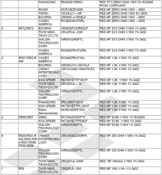
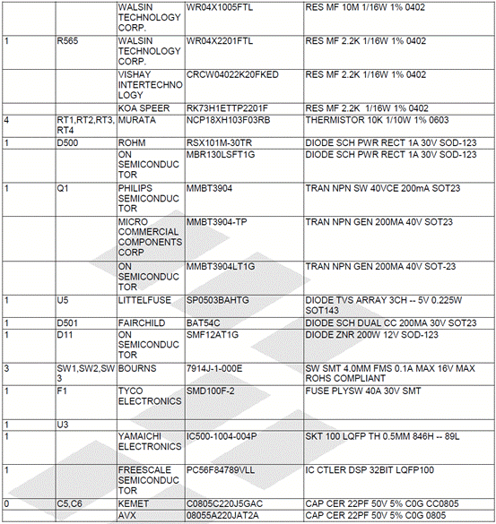
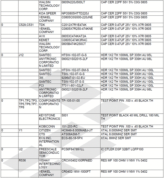
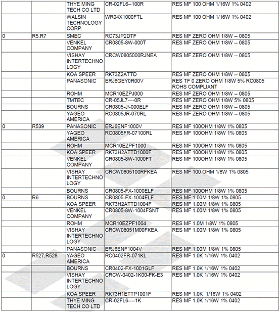
TWR-56F8400材料清单(BOM):
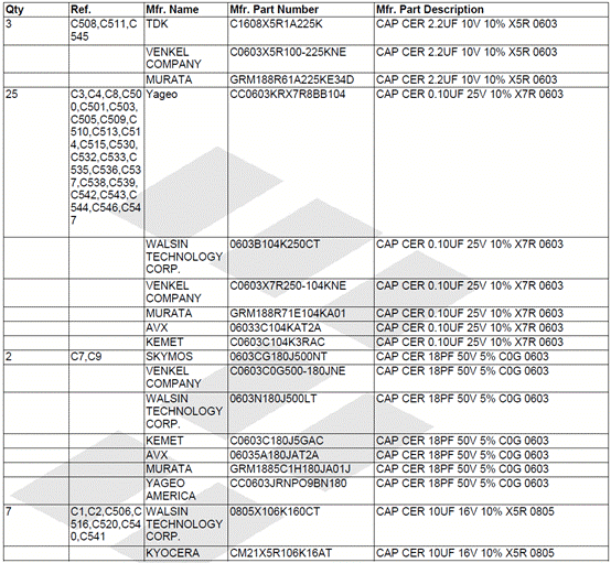
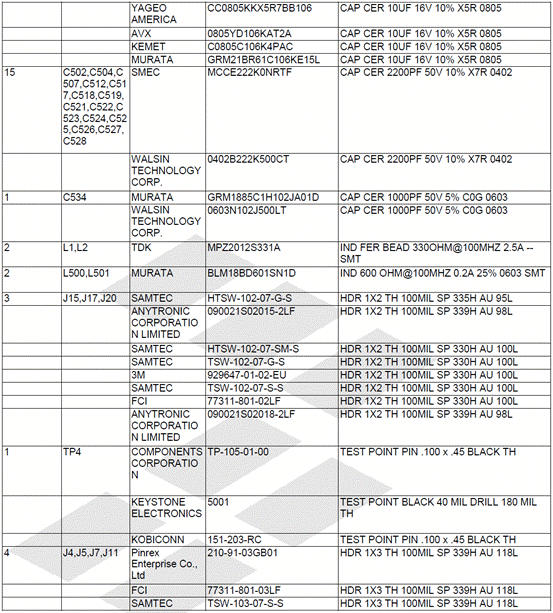



详情请见:
 MC56F844XX.pdf (1005.79 KB, 下载次数: 0) 2012-8-9 10:51:33 上传 MC56F844XX.pdf (1005.79 KB, 下载次数: 0) 2012-8-9 10:51:33 上传
下载次数: 0
下载积分: 积分 -1
和
 TWR-56F8400_UM.pdf (530.56 KB, 下载次数: 0) TWR-56F8400_UM.pdf (530.56 KB, 下载次数: 0)
来源:网络 |
|
|
|
|
|
|

